It’s a very weird assumption to begin with, but it has to be made to believe that the outcome of a scientific experiment reflects the nature of the universe.
Newtonean science is based on quantification. The term “Quantum Physics” suggests the vague realization of that, and the field is nothing but the study of the fact that science quantifies. The realization it moves toward is “in some contexts, we can’t quantify without losing accuracy.”
Can we measure without quantizing? Or, is measuring required to define?
Maybe we can define the universe only to a certain point in terms of observations. In that case RM would provide the means to arrive at that point ‘from the other side’ - reasoned from ‘nothingness’, or infinitesimal-ness.
I am afraid that I will have to insist on some reference supporting your claim. I have never found anything in QM suggesting otherwise.
Certainly true, but I suspect that you are misinterpreting what that means.
No. You are assuming that the particle and the wave being referred to are the same entity, not that there is a particle that is going the same direction as a wave. The “wave-packet” IS the particle. There is no other wave involved.
True, but irrelevant.
That is where an error in understanding has occurred. There is no “forward direction” involved other than the particle itself. And any notion of the particle going in the reverse direction of the particle is of course, absurd.
That would directly imply that the particle is headed in the opposite direction of the particle.
Then TEW disagrees with fundamental QM, not merely adding another entity to it. So the question becomes, “what is a particle in TEW?”
The 4 theories, and yes.
I don’t think so.
Newtonian physics merely says that things are measurable. It makes no claim that there is a minimum size concerning anything.
A “quanta” in QM refers to an indivisible size, length, or time.
Plank’s length is a proposed length that cannot be divided.
Plank’s time is a proposed time that cannot be divided.
In QM, there is no such things as PL/2 or Pt/2.
We can’t document with decimal numbers without quantizing. But we can say, “the circumference divided by the diameter” and we have referenced an infinitely long decimal number. That alone is enough to show that QM’s proposal is nonsense.
Your last post clears up the wave direction issue for quantum mechanics (qm).
You wrote:
We are in agreement: qm claims the wave and the particle are the same thing. Hence the wave is going in the same direction as the particle.
We can detect particles, but we never actually detect a wave - we only see effects that strongly suggest a wave is involved. Think about it - we can’t see the wave. By saying the wave is going in the same direction as the particle, qm is making an assumption.
The Theory of Elementary Waves (TEW) challenges that assumption. Why?
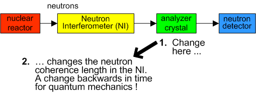
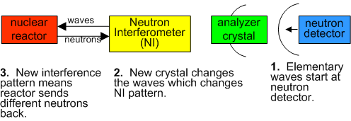
One experiment shows it clearly. We send neutrons from a reactor to a Neutron Interferometer (NI) then to an analyzer crystal then to a detector.
This experiment is written up (from the qm point of view) here:
For qm, everything is going left to right. Then we change the analyzer crystal. Immediately, the coherence length of the neutrons changes in the NI.
How can something on the right affect something on the left? For qm, this change is backwards in time. For qm there is no choice - how else can the effect happen? This is discussed by the experimenters on page 41 (italics in the original) :
The TEW assumption about wave direction makes a huge difference to the explanation. For TEW, elementary waves are going right to left. That is how the analyzer crystal affects the NI.
The full TEW explanation is that elementary waves are leaving the neutron detector. The analyzer crystal affects those waves, just like a lens affects light. The new analyzer crystal changes the elementary waves, which then have a different interference pattern in the NI. This leads to a different pattern of elementary waves reaching the source, which sends a different set of neutrons (with a different coherence length). Hence the result. Everything happens in normal time.
The values for neutron coherence length are in Table VIII on page 41. It is clear that qm cannot explain the numbers, but TEW can.
Fixed Cross - I believe this experiment is directly relevant to your work on value ontology. The elementary wave explanation gives a clear cause and effect. Have you read the TEW book yet?
This experiment is very clear evidence that the TEW assumption on wave direction is correct. The alternative is that you believe something happened backwards in time.
And as far as I can tell, TEW does not dispute that. When TEW says that “A wave” is going in the reverse direction, it is merely saying that there is a elementary wave that is going in the opposite direction as the particle. If there were the slightest hint anywhere else in physics that such a wave existed, TEW might have a chance. But the notion of “a magic marker wave luring particles to their destiny” is a bit much, even for QM fanatics.
No. Again, QM is merely saying that the particle IS a wave-packet. That is the assumption (and at first a reasonable one). Of course the wave that is the particle is always going in the same direction as the particle because that wave and the particle are the same thing. Else you would be saying that even though your physiology was going to the left, your body is going to the right.
No. I don’t think that Dr Little challenges that “assumption” at all. He is merely proposing that a new kind of wave exists that carries a magic marker from the screen to the particle source, inspiring the particle to follow its path back to the particle’s new home, much like casting a fishing line and reeling in the fish.
You cannot use such simple pictorials to compare theories or justify anything. There are far too many hidden (from the viewer) variables involved. But with that TEW explanation, I have to wonder how the magic wave manages to go through all of the materials involved in order to let the particle know which path to take. By the time the particle got on its way, the same path wouldn’t be clear anymore. Within the materials, electrons are spinning at near light speed and the atoms are vibrating all over the place. It seems to me that the elemental wave would have picked up a new magic marker by the time it got to the particle source. There is just way too much going on inside those blocks for such an example to be useful.
The simple diagrams I provided are very useful. The whole point of showing this experiment is to highlight how quantum mechanics (qm) has an assumption about wave direction - that the particle and the wave are the same thing.
In the 1920s, the founding fathers of qm - Neils Bohr and Werner Heisenberg made that assumption, and everyone since has accepted it without being aware. This is the moment that qm forgot philosophy. Instead, qm worshiped mathematics which gave the correct probabilities for experiments like the double slit. Since the maths was right, qm felt convinced that no doubt could be brought to bear on their explanations. For qm, the crowing glory is Quantum Electro-Dynamics where they can at times be accurate to 11 decimal places. So they believe their assumption about wave direction is right (even though they’re not aware it’s an assumption).
The neutron experiment I outlined in my last post shows the consequences of that assumption. For qm, the effect must be happening backwards in time. You can look up more complicated diagrams if you like - see the experiment and the TEW (Theory of Elementary Waves) book which give more details. Nothing can save qm from the reality that they can only explain the results by an effect that reverses time.
In contrast, the TEW wave direction means that everything happens in normal time. The details are in the TEW book - and of course they can be nit-picked and criticized. Whatever the problems are with TEW they are nothing like the problems that qm has with time reversal.
Can anyone say how time reversal actually occurs? Of course not - qm only assumes that must be happening. The assumption about time is a consequence of the assumption about wave direction.
This is the role of philosophy in this debate - qm must be woken up from their slumber and shown they have an assumption. Considering a different assumption opens up whole new possibilities.
The good news is that TEW uses the same maths as qm. This is because of the Reciprocity theorem, which is already part of physics. Think of a wave between two points A and B. The theorem states that the intensity of a wave between A and B is exactly the same as the intensity of the same wave between B and A, no matter what objects are in between A and B. It’s the reason that radio antennas work equally well as receivers and transmitters.
For example, in the double slit experiment both qm and TEW have the same probabilities for a particle arriving at a point on the screen. Reversing the direction of the wave does not change the probability calculations. In Quantum Electro-Dynamics, TEW has the same results and precision as qm - they are equally successful.
So the mathematical precision of qm is retained by TEW. It’s only the explanations that change. The one assumption - wave direction - makes all the difference. TEW is local and deterministic, as is shown by the neutron experiment, whereas qm is non-local and includes effects backwards in time.
Of course there is more to it. You have a choice of wave directions, and you need to explore both choices before you choose which assumption works better.
The wave direction IS the fundamental difference between quantum mechanics (qm) and the Theory of Elementary Waves (TEW). This plain in the TEW book:
I can give another example of the wave direction issue, because this post will finally give the numeric examples of the geometry of the lines on the double slit experiment.
In debating this geometry, on Oct 11 you wrote:
I have been maintaining that geometry supports the lines on the interference pattern, which are based on waves traveling different paths through the slits. This post finally gives numeric examples that I have been promising.
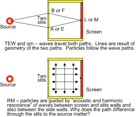
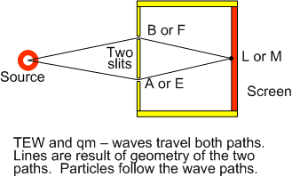
The geometry is about looking at a point on the screen. From that point there are two paths to the source – one through each slit. Both TEW and qm claim there is a wave for each path, where TEW has the wave from the screen to the source and qm has the wave from the source to the screen.
If the path difference is zero or a whole number multiple of the wavelength, then the interference is constructive. If the path difference is half a wavelength, or an odd number of that, then the interference is destructive. A key part of the design of the experiment is the setup of the screen and the slits. The slits are parallel gaps and are separated by a distance called “d”. The screen is positioned at least 1000 times d away from the slits. The source should ideally be at that distance too.
Here are the points in the examples:
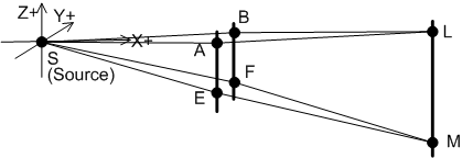
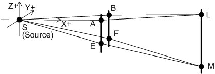
Notice we have a coordinate x,y,z system that is centered on the source (S), so S is at (0,0,0).
One slit contains points A and E. The second slit contains points B and F. Point A is on the x axis, so A always has y=0 and z=0. Points L and M are on the screen.
Slits AE is vertical, so they all have the same x and y, and only vary in their z value. Segments BF and LM are also vertical.
Point S will be the same in all examples below. In other points vary. Distance between (x1, y1, z1) and (x2, y2, z2) is SQRT ((x1-x2)(x1-x2) + (y1-y2)(y1-y2) + (z1-z2)(z1-z2)).
Visible light has the following range of wavelengths:
Violet is 380 nm = 380 x 10 e(-9) meters = 3.8 x 10 e(-7) m.
Red is 760 nm = 760 x 10 e(-9) meters = 7.6 x 10 e(-7)m.
One millimeter is 1 x 10 e(-3) m, so visible light has wavelengths 4 orders of magnitude smaller.
In the examples, all numbers will be in millimeters, unless otherwise stated. The number “d” is the distance between the slits, and is always 1.
[size=150]Example 1 - screen too close[/size]
We will make the screen so close that it does not obey the rule about the screen being at least 1000d away.
The points are as follows:
A (4,0,0)_________B (4,1,0)______L (8,5,0)
E (4,0,-3) F (4,1,-3)_____________M (8,5,-6)
So A (in a slit) is only 4 from the source. Point E is 3 below A1.
The other slit is distance 1 away (in the y direction) = distance “d”. So B has is at y =1 and F is 3 below B on the z axis.
Point L is at y=5, as is M (which is 6 below in the z direction). Point L (on the screen) is less than 7 from A. So the screen-slit distance is well short of 1000d = 1000.
L can reach the source by LAS or LBS. M can reach the source by MES or MFS.
Path lengths are below.
Paths__SQR(x2-x1) SQR(y2-y1) SQR(z2-z1) Total Path length
L-A______16________ 25________0________41____6.40312423743285000000
A-S______16_________0________0________16____4.00000000000000000000
L-A-S______________________________________10.40312423743280000000
Path Diff M-E-S to M-F-S______________________0.568924061
Difference between path diffs of L and M_______0.054240301
The difference between the path differences is about 5 x 10 e(-2) mm = 5 x 10 e(-5) m. This is about 100 times the wavelengths of visible light.
What does this mean for waves traveling to L and M? The path differences definitely matter to visible light. Depending on the wavelength involved, L and M have a different phase relationship.
This is as expected. With the screen up close like this, it is very likely there would not be an interference pattern visible. This is the intuitive result you have been pointing out.
[size=150]Example 2 - screen far enough away[/size]
We will make the screen at least 1000d away from the slits, and the same for the source.
The points are as follows:
A (1000,0,0)_________B (1000,1,0)______________L (2000,5,0)
E (1000,0,-3)________F (1000,1,-3)______________M (2000,5,-6)
We have stretched everything in the X direction, and left everything else the same.
Path Diff M-E-S to M-F-S______________________________0.003999936
Difference between path differences of L and M________1.79994E-08
The difference between the path differences is about 2 x 10 e(-8) mm = 2 x 10 e(-11) m. This is about 10,000 times smaller then the wavelengths of visible light.
What does this mean for waves traveling to L and M? The path differences make no observable difference to visible light. L and M will have the same phase relationship. If L is a bright spot, then so is M.
This is why we get lines on the screen. Vertical segments like LM have the same path difference effectively, and the same phase relationship.
Notice how the geometry has changed. Up close the vertical distance between L and M matters to the path differences, but 1000d out the vertical distance does not.
This is a fact of geometry. It may not be intuitive to some, but it is true, and all theories of physics must accommodate this.
For quantum mechanics (qm) and the Theory of Elementary Waves (TEW) the geometry is entirely consistent with the explanations. For qm, the waves are the same as the particles and start at the source and go to the screen. In TEW, the waves go in the opposite direction. The path differences are the same for both wave directions.
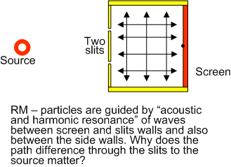
The challenge for Rational Metaphysics is to explain why this geometry applies when the waves in RM are between the slit barrier and the screen and potentially between side-walls. There are waves going everywhere except through the slits. How can the waves in RM explain why the lines on the screen are described by path lengths through the slits?
On Sep 30 (on page 25) you wrote:
This is what I call the “magic resonance”, because of the challenge in explaining the lines on the screen.
We have not seen the details of the RM explanation yet, and it may require details of experiments becoming available for RM to work on. This explanation of the lines on the screen seems essential for the publication of RM, because the double slit experiment is one of the most important physics experiments ever done.
What is important is that the geometry of the double slit experiment is something that all theories have to account for. For TEW and qm, this is clearly accounted for by the waves in those theories.
After a post I made earlier on this page, you told me that Dr Little wasn’t talking about the probability graph wavefunction. But now that I see that article, I see that he actually is. But remember this post?
It is now confirmed that Dr Little simply misunderstood QM and didn’t realize that the wavefunction is merely a GRAPH and doesn’t move in any direction.
So you can drop the whole “direction of the wave” bit because; [size=150]there is no such wavefunction direction in QM. It is a GRAPH. It doesn’t travel.[/size]
I will get to the rest of your math issues a little later.
Again, QM claims that there is a WAVEFUNCTION GRAPH that DOESN’T TRAVEL, but is merely PLOTTED through both slits.
“Ideally” the source should NOT be identically distant from the slits as the screen. I’ll explain that shortly.
There are a variety of issues in the following example, so I will merely discuss this “Too Near” example until we get some things straight.
Firstly, you have the source directly in front of one slit.
That is not the experiment and it DOES change the results by diminishing the differences (in short you have cheated).
The source is to be midway between the slots.
Secondly, You chose only one spot on the screen to compare to the horizontal plane (in blue).
That wouldn’t tell you anything, no matter what results you got.
The differences are rising and falling, thus you should expect low points as well as high points.
Thirdly, you have chosen a stipulation that hides a very important concern.
You are requiring that the distance between the source and slits be identical to that between the slits and the screen.
That creates a hidden mathematical issue as shown below;
In this graph (the brighter regions) the distance from source to slits is set to 4 as is the distance from slits to screen.
Note that the graph for the vertical indicates a straight line of no changing. That would certainly backup your claim.
But then look what happens if I merely set the slit-screen distance to 4.5 instead of 4, leaving the source to slit as 4;
Note that suddenly you have a serious interference wave going down the screen (the graph for the vertical).
You can’t merely choose a set of distances that hide your problem if you are going to prove anything.
As I said before, “Why would they hide the evidence that would prove them right?”
Similar effects occur at larger distances. It is an issue of the ratio between the two distances; source-slits, slits-screen.
If you keep those distances identical, you mask the critical evidence in most cases, but not all.
In the following graphs, the “e” value is the source-slit distance. The slit-screen distance, “d” is set to 1000.
In the first pic, there is no vertical interference pattern;
But when I set the source-slit distance to 2000 (even longer) I get this;
By choosing that the two distances are identical, you hide the issue that would make all of the difference concerning the theories involved.
You are arguing that the wave in quantum mechanics (qm) does not travel. This is the same mistake that many qm supporters are making.
The foundation of qm is wave-particle duality, and it is evident in that every textbook on qm has the principle. That is how qm was developed and “explains” the wave behavior of matter. As soon as you say the wave and the particle are the same thing, you have assumed the direction of the wave.
In the neutron experiment I mentioned (Kaiser et al 1992) the experimenters talk about “matter waves”. For qm, how could the direction of the wave be anything other than the direction of the neutrons?
The experimenters clearly relate the quantum wave to the neutrons. Their thinking is that the neutron is a wave packet with a coherence length. This is no mere graph - it is the neutron itself. This is shown in their quote from page 41 if Kaiser et al:
That quote gives away that they believe the wave packet is physically real and has a direction.
The mistake that the qm supporters make is to get over confident and forget the foundations of their own theory. Because the mathematical results are so precise, qm supporters forget physical reality and claim that the quantum wave is just a wave of probability and, like you say, has no direction. It’s an example of qm supporters abandoning philosophy. It is yet another reason why qm does not make sense.
Think of the implications in Kaiser et al if the quantum wave for a neutron is only a wave of probability. If a quantum wave has no direction and is only a graph, where did the mass and energy of the neutron go? If the mass and energy are unchanged in the neutron, how does the probability graph control the coherence length of the neutron? If the neutron is both mass/energy and a probability wave, how can that be? We only ever detect the mass and energy of the neutron, so what controls switching between mass/energy and a probability wave, and how does one affect the other? Describing a quantum wave as merely a graph with no direction raises more questions that in answers.
In qm, there are plenty of other examples of over-confidently abandoning foundations. My favorite is Schrodinger’s Cat. Schrodinger was trying to point out that the qm idea of “superposition of states” makes no sense, because it doesn’t describe the cat’s state. So the Schrodinger’s Cat example shows that qm is invalid (again). However, qm supporters mention it like a strength (!) simply because the qm probabilities work, not because qm makes sense.
Forgetting basic logic and their own foundations is a qm habit. Like the emperor with no clothes, one day people will wake up and realize how embarrassing the last 80 years has been in physics. Even the mightiest natural science of them all can make mistakes, and this one is truly gigantic.
There is a silver lining to this mistake. Hey - let’s encourage qm supporters to think that the quantum wave has no direction - go for it James. If qm supporters think that the quantum wave has no direction, it’s only another short step to considering that the wave might travel in the opposite direction. That’s what qm needs - a reason to start considering something that they have clearly never thought about before.
Yes, Dr. Little did definitely develop the Theory of Elementary Waves (TEW) starting with the idea of the quantum wave traveling in the opposite direction. There’s more to TEW, of course. It’s really important to see that first step in developing the theory.
On Page 2 of the TEW book, Dr. Little writes:
He goes on to show the huge number of contradictions that qm leads to, like particles being in two places at once, effects backwards in time, multiple interpretations and so on. Dr. Little also shows what we can see the particles, but never the quantum wave, so how do we know what direction the wave travels in? He shows various experiments that contradict the idea that the wave travels with the particle (like the neutron experiment Kaiser et al).
On page 26, Dr. Little writes:
It’s the first step in understanding how TEW is an alternative choice to qm - they have the same mathematical precision, it’s only the wave direction and explanations that are different. The different wave direction makes TEW local and deterministic, whereas qm is proudly non-local.
I will prepare some more numeric examples to clear up your issues with my first set of examples. You are claiming there are problems when there are none.
No. That mistake is yours and his. It is a common mistake in QM, but not by the original theory.
No. That is what I have been talking about for that last half-dozen posts. You aren’t paying attention.
In QM, the particle IS a wave balled up, “packeted”. That particle/wave travels along the path to the screen, through ONE of the slits. But the detectability of the particle/wave is a “wavefunction” graph. That graph is the one that goes through both slits because it is merely plotting all possible paths for the particle/wave to travel. By closing one of the slits, the “wavefunction collapses” because one of the paths is no longer possible. But changing one of the slits has no affect upon the particle/wave that is going through the open slit.
Again, in QM, there are two waves involved.
The particle itself as a packeted wave.
The probability wavefunction graph that plots through both slits.
The only wave that is actually traveling is the particle/wave as a small packet. It is because the wave is packeted (by their theory) that the detection problem arises and creates the probability plot.
Many less educated people today have thought and even been taught that the wavefunction is a physical wave. They were taught or they speculated wrong. It is a long standing misunderstanding. The particle is one wave. The probability plot is a different wavefunction. The wavefunction does not travel at all. It is merely a plotted graph.
Yes. The particle/wave is a “wave packet”. It is a small balled up wave (according to their theory). That small ball travels and it was their speculation that because it is a packeted wave, when it encounters another of its own kind, the wave inside each might be out of phase and thus do as the photons and cancel each others affect. That would lead to the interference pattern effect. But it is not the wavefunction plot that is combining in that case, but two particle/waves.
When they fired only one particle/wave at a time, it was only the wavefunction plot that could explain the interference pattern so they proposed that the particle/wave goes in and out of existence according to the detectability. That was a new idea added to the original. But anyone with half a brain can see through that nonsense. What they teach in universities is a conflating of both concepts that confuses everyone and that is apparently what they wanted to do (thus the “Shutup and Calculate” school).
I certainly agree with that. But I am talking about before that time when the educated physicists knew the difference between a probability plotted wavefunction and a packeted wave. The two concepts go together because if the particle is a packet wave, then the probability wavefunction is a necessary result.
You are the one competing with them. I am not. I am not trying to change the minds of drones (with the possible exception of you ).
I have to ask why you are ignoring the equations and math that I am providing that give far more detail than the ones that you are coming up with.
You were describing the quantum mechanics (qm) explanation involving a wave function of probabilities somehow guiding one wave-particle, and you wrote;
The nicely summarizes the qm explanations - they are a confused combination of concepts.
You are referring to the quantum wave function usually given by the greek letter psi, and the square of that function gives the probability. Yes, psi squared has no direction - just a number.
The real quantum wave is the de Broglie wave. This is a relationship between the momentum of the particle to it’s wavelength. Everyone in qm has assumed that the wave is traveling in the same direction as the particle. That is the core assumption of qm. This assumption happened before the development of psi. The qm world has forgotten this, and just thinks about probabilities which have no direction.
It is qm that is confused and needs to look at it’s own foundations and assumptions. The wave direction is critical to qm, and they have never thought about that idea.
I will get to your issues about the path lengths in the double slit experiment. You have made some many claims that I will need to slowly go through them all when I get enough time.
The “momentum” includes direction. The direction they are talking about is merely the direction of the particle/wave, not the direction of the probability plotted graph.
Btw, RM operates on a level so precise as to make any comparison between RM and QM like trying to compare an F18 to a dirigible. QM must keep adding hot air into their theory in order to keep it afloat amongst the clouds of confusion. RM has one firmly defined concept (“Affectance”) from which all else is unavoidable logical consequence.
And I have found some words to help convey the concept of Affectance;
You have mentioned two important ideas in your last post.
Firstly, your wrote:
This is the classic quantum mechanics (qm) assumption: that the wave must be in the same direction as the particle because the particle has momentum. This is where qm forgot philosophy - we cannot see the wave directly, so we can’t be totally sure of the direction. The Kaiser et al 1992 experiment with neutrons is a big hint that the wave is in the opposite direction. All it takes is standing back and having second thoughts about the wave direction. It’s hard to do, and that’s why qm has been unchallenged for about 80 years.
The second thing you wrote was:
The big point about that probability is calculated from psi squared. If the probability is 9 there are two solutions: 3 and -3. That is symbolic of qm not considering the other wave direction. The other solution has been there all the way along, but never considered.
Of course probability has no direction. Talking about a “probability wave” is meaningless - it is just a graph of psi squared. Is the direction of psi by itself that matters.
All this has been right in front of our faces all the way along.
I have no comments on your definition of affectance. You still have lots more to talk about on Rational Metaphysics (RM).
On October 18 you raised some issue with my numeric examples of the path lengths in the double slit experiment. You wrote:
This is very easy to answer. Let’s re-do my two examples with the source midway between the slits.
Here is the new diagram of the points:
As before, we have a coordinate x,y,z system that is centered on the source (S), so S is at (0,0,0).
Distance between (x1, y1, z1) and (x2, y2, z2) is SQRT ((x1-x2)(x1-x2) + (y1-y2)(y1-y2) + (z1-z2)(z1-z2)).
In the examples, all numbers will be in millimeters, unless otherwise stated. The number “d” is the distance between the slits, and is always 1.
[size=150]Example 3: screen close in and source midway[/size]
Let’s move all the points 0.5 lower in the y direction. How the source is now midway between A and B (both are distant from the source 4 in the x direction and 0.5 in the y direction). L and M are also moved the sane amount in the y direction, so the relative places of A,B, L and M are unchanged.
The points are as follows:
A (4,-0.5,0)________B (4,0.5,0)___________L (8,4.5,0)
E (4,-0.5,-3)_______F (4,0,5,-3)__________M (8,4.5,-6)
The difference between the path difference is about 8 x 10 e(-2) mm = 8 x 10 e(-5) m. This is about 100 times the wavelengths of visible light. So as before, with the screen close in it appears unlikely there would be an interference pattern.
[size=150]Example 4 - screen further out[/size]
We will make the screen at least 1000d away from the slits, and the source at least 1000d away from the slits, still with the source midway between the slits.
The points are as follows:
A (1000,-0.5,0)________B (1000,0.5,0)___________L (2000,4.5,0)
E (1000,-0.5,-3)________F (1000,0,5,-3)__________M (2000,4.5,-6)
We have stretched everything in the X direction, and left everything else the same.
The path lengths are below.
The difference between the path differences is still about 2 x 10 e(-8) mm = 2 x 10 e(-11) m. This is about 10,000 times smaller then the wavelengths of visible light. Hence points L and M would have the same phase relationship – if L is a bright spot then so is M.
As you can see, putting the source midway between the slits has not changed the results in a meaningful way.
It makes sense logically. Placing the source midway between the slits was just a useful strategy by experimenters to ensure the path differences that matter are those between the slits and the screen. It is not necessary to position the source that way. Also think about the implications if it was necessary – how exact would it need to be? Less than a wavelength of visible light? It would be very difficult to see an interference pattern in the experiment if the position of the source was so critical.
That clears up your first issue. I will answer your other issues in later posts.
You took care of only one of the 3 issues, the first one and least significant. And btw, I have noticed, in case you want to use it, in my diagram where I have " f = e/d * z ", that should have been " f = e/(d+e) * z ". Because I didn’t actually need that formula, it didn’t affect my graphs.
[size=150]In addition, you keep mentioning the number of waves lengths which has nothing to do with it at all.[/size]
The issue is merely the [size=150]sine of each length added[/size] (although they actually should be multiplied due to it being a probability issue).
Also now that you have the source properly half way between the slits, you can leave out your A-S and B-S lengths because they will always be identical, as well your E-S and F-S. Because they are identical, they do not contribute to the differences being measured.
[size=150]My graphs are showing 400 points down a chosen column.[/size]
I have to ask why you are ignoring the equations and math that I am providing that give far more detail than the ones that you are coming up with.
Try these points your way;
A (4.5,-0.5,0)__________B (4.5,0.5,0)______________L (8.5,-0.5,0)
E (4.5,-0.5,-12.7)_______F (4.5,0.5,-12.7)__________M (8.5,-0.5,-24)
We are debating the lines on the double slit interference pattern.
I am arguing that the lines reflect the path differences of waves going through the slits, as shown in this diagram:
To show the path differences, I have applied a simple formula for the distance between two points. So far, I have shown that there is no interference pattern when the screen is close in. When the screen is at 1000d the points L and M have the same path differences as far as visible light is concerned - hence the lines on the pattern. This is a geometric argument shared by mathematics and both quantum mechanics (qm) and the Theory of Elementary Waves (TEW).
You raised an issue about the source being opposite a slit, and I showed it makes no difference.
You have raised more issues on October 18 which I am working through. In your last post you have raised even more issues.
Among your latest issues is pointing out your calculations use different formulas. It’s one issue I was going to get to, and I will mention now. It is clear that the paths are easy to calculate by the coordinates and formula I have shown. Instead, your posts break down the paths into triangles and calculating each side and so on, which is completely unnecessary.
Calculating probabilities is not the primary issue - the primary issue is the path lengths, which lead to phase differences for visible light and this affects the probability of a bright spot or not.
Your posts also want to use the sine function - also completely unnecessary to calculate path lengths in the simplest way I have shown.
Your argument is trying to complicate the issue, snow everyone and scare off philosophers, who usually don’t like formulas. All this is an attempt to distract everyone from the fact the Rational Metaphysics (RM) has no clear model yet for why the path differences matter. RM claims that acoustic and harmonic resonance is the reason for the interference lines, and I call this “magic resonance” because it is not clear how this works.
There are also subtle distractions mixed in to your posts. Your last post suggested some points to calculate distances for. The points on the screen are close in - way short of 1000d, so there is no need to calculate anything - we know there is no interference pattern there.
As well, you can see on my diagram that the gradient from M to E and F is the same as the gradient from E and F to S. Your diagrams includes examples where this is not true - the equivalent of M is too low (below a direct line through the slit). Your argument cannot use such an example - it would need experimental results to prove they exist. The only points that we all agree exist are where there is single gradient from the source through the slits to the point on the screen. By throwing in other points your argument is wasting everyone’s time.
As well, by showing graphs of sine waves your argument is once again only describing a short distance from the slits to the screen. There is no point trying to show graphs of sine waves for points at 1000d. Such diagrams take up space and do not calculate any path differences.
I will proceed to your other issues from Oct 23 and your last post in due course. There are so many distractions it takes time to step through them all.
Eugene, you really should be embarrassed for making that post.
You did not do as you claimed in that post.
I did not do as you accused in that post.
And distracting and shifting the subject back onto RM would not resolve the issues that I raised concerning your theory.
The issues raised;
the distances between source-slit and slit-screen cannot always be identical, else you haven’t proven anything.
you cannot merely show one convenient point on the screen and claim that you have proven anything either.
On the other hand, I provided you with a specific point on the screen and set of distances that demonstrates that the presumed theory would fail to work at that point. Of course there are very many other points, as my graph demonstrates. But you want to do one point at a time.
I have not claimed that I have proved very much yet. All I have shown so far is:
When the screen is close, an example of L and M have very different path differences, and hence a different phase relationship (as expected).
When the screen is at least 1000d away, the same example arrangement as in (1.) above now has L and M with the same phase relationship. The distance of 1000d made a dramatic difference to the phase relationship. According to your argument, the distance of 1000d should not have affected this.
The position of the source - opposite a slit or between the slits did not materially change the result of the example in (2.) above.
According to your argument, my examples in 2 and 3 should not have worked, unless I had fluked a combination of L and M where the “up and down” change to the path differences meant both L and M were at the same point in that change cycle.
My next task is to show that if there is any “up and down” change to the path differences at 1000d, then it is too small to affect the phase relationship. I’ll need a lot more examples, and so it will take some time. I will need to try a lot more choices of M to show that L and M always have the same phase relationship.
After that I will look at other issues, such as whether the source needs to be 1000d away from the slits. It can all be sorted out using the coordinate system I have chosen.
It only takes one “flaw” to invalidate a theory. The closeness should not make any difference in the vertical columns. But it does.
No. I made no such argument.
If the screen is 1000d away, set the source a 2000d away and you will find many points on the screen out of phase along the same column. Again, the theory is that such could not occur. But it does.
That is not my argument.
At any one distance setting, you can find points where the phasing is not out.
The problem is that you have to show that they are never out along any one column.
You can’t prove that something is always true unless you prove that the converse is never true.
I used the column that is directly in front of one of the slits. That column is important and it also makes some of your math a little simpler. It doesn’t really matter which column you use because the theory has all columns uniform from top to bottom. In the case of 1000d slit-screen, that column will not show phase variations if the source is also exactly at 1000d. But if you set the source even further away at 2000d, that column suddenly looks just like a horizontal row with phasing going in and out.
It isn’t how far away. It is the ratio of source-slit to slit-screen. If you make those identical, you hide the problem from yourself. Or at least you will hide it if you use the column directly in front of one slit.
Actually, now I have altered the program to allow me to set which column on the screen to calculate. Given a column offset, it will plot 400 points down the column.



 ).
).