New theory of quantum world

James,

You have reminded me of another set of cases I will cover - the source is at a different distance to the screen. I can make it twice the distance or any other combination. There are a lot of cases to cover, so I’m not there yet in preparing my examples.

All your issues have a common theme - you are assuming that problems that exist when the screen and source are up close to the slits will still occur when the source and screen are 1000d away. It’s not true, and that’s clearly going to be a challenge for you to accept, even when the evidence is presented. What is important is that the geometry is based on logic and facts - exactly what you claim Rational Metaphysics is based on, so you should be able to relate to the geometry when I show it to you.

Eugene Morrow

If you had bothered to look at the graphs that I already supplied, you could see that I already plotted 2000d x 1000d.
The ratio of 2:1 will show the problem dramatically. But you still have to look at more than a single point.

After I modified my program to allow me to put in any column, I couldn’t find any column that would display the problem as long as the ratio was 1:1. The further from that you get, the more obvious the problem is and it shows up on every column in each case.

So good luck with that one.

James,

We have been looking at the lines on the double slit experiment. We have been discussing the source at twice the distance from the slits as the screen.

In your last post you challenged me:

Let’s look at some examples using my coordinate system. As usual the points are as follows (not in proportion):
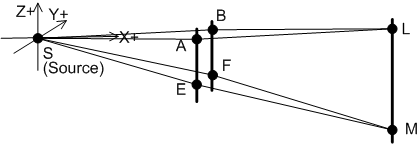
Num_01_Coords_04.gif

As before, we have a coordinate x,y,z system that is centered on the source (S) at (0,0,0).
Distance between (x1, y1, z1) and (x2, y2, z2) is SQRT ((x1-x2)(x1-x2) + (y1-y2)(y1-y2) + (z1-z2)(z1-z2)).

Visible light (used for the double slit experiment) has the following range of wavelengths:
Violet is 380 nm = 380 x 10 e(-9) meters = 3.8 x 10 e(-7) m.
Red is 760 nm = 760 x 10 e(-9) meters = 7.6 x 10 e(-7)m.

In the examples, all numbers will be in millimeters, unless otherwise stated. The number “d” is the distance between the slits, and is always 1.

As usual, we need the screen and the source at least 1000d from the slits. The gradient from M to E,F must be the same gradient from E,F to the source. This means the spacing in the z direction is the same as the spacing in the x direction.

[size=150]Example 5: Source at 2000d, screen at 1000d[/size]
The points are as follows:
A (2000,-0.5,0)________B (2000,0.5,0)___________L (3000,4.5,0)
E (2000,-0.5,-4)_______F (2000,0.5,-4)__________M (3000,4.5,-6)

The paths differences summary is:

Path Diff L_A_S to L-B-S________________0.004499954
Path Diff M-E-S to M-F-S________________0.004499945
Difference between path differences____8.99945E-09

The difference between the path differences is even smaller than before: 9 x 10 e(-9) mm = 9 x 10 e(-12) m. This is about 100,000 times smaller then the wavelengths of visible light. Hence points L and M would have the same phase relationship – if L is a bright spot then so is M.

Let’s be devil’s advocate here – perhaps the “up and down” changing of the path length differences is happening in between L and M, and I’m just lucky that M is back to the same path difference as L.

To check this out, let’s look at the points in between L and M. The only difference between them is in the z direction: L is at 0 and M is at -6. Let’s try M at -1, -2, -3, -4, and -5 to see if we can see some sort of up and down change.

[size=150]Example 6: M at -1[/size]
A (2000,-0.5,0)___________________B (2000,0.5,0)____________________L (3000,4.5,0)
E (2000,-0.5, -0.666666667)________F (2000,0.5,-0.666666667)__________M (3000,4.5,-1)
Path_Diff_L_A_S_to_L-B-S_______________0.004499954
Path_Diff_M-E-S_to_M-F-S_______________0.004499954
Difference_between_path_differences____2.49656E-10

[size=150]Example 7: M at -2[/size]
A (2000,-0.5,0)___________________B (2000,0.5,0)____L (3000,4.5,0)
E (2000,-0.5, -1.333333333)F (2000,0.5, -1.333333333)M (3000,4.5,-2)
Path_Diff_L_A_S_to_L-B-S
0.004499954
Path_Diff_M-E-S_to_M-F-S
0.004499953
Difference_between_path_differences
9.99535E-10

[size=150]Example 8: M at -3[/size]
A (2000,-0.5,0)____B (2000,0.5,0)L (3000,4.5,0)
E (2000,-0.5, -2)F (2000,0.5, -2)M (3000,4.5,-3)
Path_Diff_L_A_S_to_L-B-S
0.004499954
Path_Diff_M-E-S_to_M-F-S
0.004499952
Difference_between_path_differences
2.24964E-09

[size=150]Example 9:– M at -4[/size]
A (2000,-0.5,0)___________________B (2000,0.5,0)____L (3000,4.5,0)
E (2000,-0.5, -2.666666667)F (2000,0.5, -2.666666667)M (3000,4.5,-4)
Path_Diff_L_A_S_to_L-B-S
0.004499954
Path_Diff_M-E-S_to_M-F-S
0.00449995
Difference_between_path_differences
3.9995E-09

[size=150]Example 10: M at -5[/size]
A (2000,-0.5,0)___________________B (2000,0.5,0)____L (3000,4.5,0)
E (2000,-0.5, -3.333333333)F (2000,0.5, -3.333333333)M (3000,4.5,-5)
Path_Diff_L_A_S_to_L-B-S
0.004499954
Path_Diff_M-E-S_to_M-F-S
0.004499948
Difference_between_path_differences
6.24914E-09

Here is the trend:
Z coord of M _______Difference between path differences (mm)
-1_______________________2.49656E-10
-2_______________________9.99535E-10
-3_______________________2.24964E-09
-4_______________________3.9995E-09
-5_______________________6.24914E-09
-6_______________________8.99945E-09

What does this show? The phase difference gets bigger between z coordinates of -1 to -6, at a slowing rate. All of the phase differences are at least 100,000 times smaller than a wavelength of visible light, so they do not matter. If L is a bright spot then so is M.

In conclusion, moving the source at 2000d from the slits and the screen at 1000d has dramatically shown there is no problem whatsoever - the interference lines on the screen make sense.

You will have to show us your calculations, so we can see the problem you are talking about.

Eugene Morrow

The way this game of comparing favored theories is that when I am talking about my theory, you get to make me jump through hoops as long as you listen and grasp what I am actually saying before trying to correct it. And when you are talking about your theory, the revere is true, I get to make you jump through hoops… such as;

A) the light wavelength is irrelevant. You have the slits set at “one wavelength” apart (or you can choose more).
B) you have to add (or multiply) the sine’s of each length, not merely the distances. They are sine waves.
C) at -6 you should have a length difference of

LA-LB = ( 1000.0080 - 1000.0125) = 0.00450
ME-MF = ( 1000.0170 - 1000.0125) = 0.00450

You should be showing no difference in the differences at all.

But you have to take the Sine of the lengths (although I use Cosine just so I will start with 1 rather than 0. It merely flips the graphs upside down.);
LA-LB = ( 0.999807243 - 0.999921045) = -0.000155741
ME-MF = ( 0.999643488 - 0.999807243) = -0.000163755

The cosine of each length shows a difference of 0.00004995

You won’t see the differences if you don’t look at the sine waves. You insisted on the issue of “sine wave” for two weeks. You are not allowed to drop it now.

But on a different note;
When I said that I had found an error on my graph page concerning “f = e/d”, I thought that I hadn’t used that anywhere in the rest of the program. I discovered that actually I had used it. So when I put the proper formula in the rest of the program, I got slightly different results that actually make a little more sense to me logically.

Rather than the 2000:1000 ratio showing the problem more greatly, it is actually the other way around. A 1000:2000 will show it more greatly (sorry about that), but once you use the proper sine function, not merely the differences in length, even the 1000:1000 ratio shows the problem (using your column at 4.5) as seen below.

With the corrected formula the phasing that was in line at the horizontal is 100% out of phase at 89 wavelengths down the column. In order to hide the problem, just make the source very far away from the slits compared to the slit-screen distance (like 10:1).

James,

Your points in our last post show why we are getting such different results.

You wrote:

You are completely wrong on this. We are debating the known interference patterns found in the double slit experiment, and that means using the parameters that are already documented - visible light and a slit separation in the millimeter range. If one wavelength is one millimeter you are describing an experiment with microwaves, and I doubt the experiment has ever been performed because you can’t see the results directly. Unless you can quote an example of exactly this configuration, you are speculating on the results of a new experiment.

Using the sine function is unnecessary, even though light waves are sine waves. All that is needed is to calculate the critical value - the difference in the path differences for L and M. This is compared to the wavelength to see if L and M would have a different phase. Since the critical value is less than 10,000 times the length of one wavelength in examples 2, 4 and 5-10 then there is no need to calculate the phase difference using the sine function - it’s too small to bother with.

What are the coordinates of A,B,E,F,L and M are you using here? It’s not clear to me.

Eugene Morrow

No we aren’t.
We are talking about simple geometry involving two sine waves.

I just showed you an exact example of how the differences alone do not reflect the actual concern which is entirely one of adding sine functions. And they are NOT sine waves of light. They are graphs.

James,

You stated:

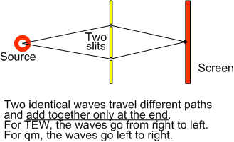
Now I understand why you are so confused. The explanation of the double slit experiment for both quantum mechanics (qm) and the Theory of Elementary Waves (TEW) is based on two waves that are identical - one through each slit:

TEW and qm waves 01.gif

What is important is clearly shown on the diagram: the waves are entirely separate until they reach the end of the two paths. TEW and qm only disagree on the direction of the waves.

You want to add up the sine waves along the entire journey, which is not relevant. The graphs you show of added sine graphs do not prove anything.

To understand the TEW and qm explanation of the interference lines in this experiment, start with the diagram above. The basic issue is comparing the wavelength to the difference in path lengths only at the end point.

The experimental results show the extra factors required:
(1) The separation between the slits = “d” is of the order of a millimeter
(2) The distance to the screen which is at least 1000d
(3) The distance to the source which is at least 1000d
(4) The wavelengths used - visible light - which are at least 100,000 times smaller than d.

This is useful to clarify, so you know the parameters for Rational Metaphysics to cover this experiment.

Eugene Morrow

They are two SINE function GRAPHS. They are not light waves. Besides which we are talking about the particle experiment, not the light experiment.

Eugene, the sine function yields a graph that shows the sine value along the entire path from 0 to x, hence “sin(x)”. To know the value anywhere along the line, you simply take sin(x) for x = the point you want to know about. To know what the value is at the end of the line, you merely take the sin(x) for x = end of line.

If you happen to know the wavelength involved, you could go to the trouble of truncating all but the last incomplete wavelength. But you would get the exact same result. The sine function repeats its values after each complete wavelength.

We aren’t even talking about a light experiment so it doesn’t matter what the wavelength of light is. We are talking about the geometry involved in connecting sinusoidal graphs in 3 dimensions. But the experiment that is relevant is the particle experiment, not the light experiment.

James,

You keep on surprising me with your posts about the double slit experiment.

As you know, both quantum mechanics (qm) and the Theory of Elementary Waves (TEW) explain the double slit experiment using waves through the slits, even if particles travel from the source to the detector or screen.

In qm, the principle of “wave-particle duality” applies, so a particle is also a wave, either as a wave-particle or a wave packet. The waves travel in the same direction as the particle from the source through the slits to the screen where they interfere.

In TEW, elementary waves travel from the screen through the slits to the source. The intensity of the elementary waves interfering at the source stimulates particles which follow the stimulating wave through one of the slits back to the point on the screen where the wave emerged.

So both qm and TEW agree that using particles in the double slit experiment still involves two identical waves through the slits. The original and most common type of double slit experiment is with light waves, and that is the best documented and understood. As we know, light can be described as sine waves or as photon particles.

Both qm and TEW use the same arguments to explain the interference lines on the screen. The wave direction is the only things that separates qm and TEW, and wave direction makes no difference to the path lengths or the phase differences when the waves combine.

You wrote:

The sentence is meaningless, because light can be described as both waves and particles.

The double slit experiment is always talking about both particles and waves - that’s why the experiment is famous and fascinating. There is no getting around it - any theory must explain what happens with light, whether it’s qm, TEW or your theory of Rational Metaphysics (RM).

You wrote:

Yes, the sine waves for qm and TEW can be described as graphs if you want to. That doesn’t change the explanations or their success.

You wrote:

Yes, that’s how sine waves work. Yes, the end of the path length is the bit we’re interested in.

Yes, I made a mistake with the magnitudes of the wavelengths of light. Light has these wavelengths:
Violet is 380 nm = 3.8 x 10 e(-7) m.
Red is 760 nm = 7.6 x 10 e(-7)m.
One millimeter is 1 x 10e(-3)m, so light is at least 1,000 times smaller.

You wrote:

We are always talking about two identical waves through the slits, and the wavelength changes the dimensions of the sine wave, so it’s always relevant. The interference when the two waves combine again depends on the wavelength.

You then write:

You are tying yourself in knots here: light (which you deny we are talking about) is an example of connecting sinusoidal graphs in 3 dimensions (which you say we are talking about).

Then you write:

This is the meaningless sentence again.

This whole debate started because you claimed that qm and TEW should result in concentric circles on the screen. Yet all my numeric examples that meet the conditions of the experiment (Examples 2, 4, 5, 6, 7, 8, 9 and 10) show the lines make sense because of the path differences and wavelengths. Examples 5 to 10 all have the source at 2000d, and the lines are still explained. So far qm and TEW have demonstrated their explanation works.

You have not yet demonstrated any concentric circle. Are you still claiming that qm and TEW have got it wrong? If so, why?

Eugene Morrow

Eugene, we are talking about combining graphed sine waves and/or physical elementary waves, neither of which do we know the wavelengths involved. But we don’t actually care because we are not trying to deduce the exact distances between the interference pattern strips. Any wavelength will do. Different wave lengths merely require different distances so as to show the same interference pattern. They do not change the geometry issues.

So have you worked out the vertical interference issues yet?

James,

For the double slit experiment, the wavelength of the light used applies to both quantum mechanics (qm) and the Theory of Elementary Waves (TEW). For TEW, the wavelength of the elementary waves is the wavelength of the light involved. For both qm and TEW the wavelength is known, and so the geometry works as shown in my examples with the coordinate system.

My examples show that when the experimental conditions are met, then points L and M have the same phase relationship. M is vertically below L which shows the vertical lines on the interference pattern make sense, purely based on calculations of path differences and the wavelength of light.

What vertical interference problem remains, from your point of view?

Eugene Morrow

There is no light involved.

The QM sine wave is a probability calculation.
The TEW elementary wave stems from (or through) particles, not sources of light.
The experiment sources particles toward the slits and screen.

No “light”… anywhere.

For one point on the screen only. But even in that, you did not add the sine as you must. You merely added the distances and proclaimed that what was left is “insignificant” - WRONG.

And there is no LIGHT.

The fact the the vertical columns display an interference pattern (that you are now desperately trying to avoid).

I gave you a specific point where the phasing is out.

James,

You have not given a clear example of your argument.

You finished your last post saying:

Where is the example of an interference pattern down a vertical column?

Let’s look at your previous examples. On Oct 23 you wrote:

These points are far closer than 1000d so they are not an example of an interference pattern.

On Oct 27 you wrote:

I asked you the full coordinates of those points, but you have not supplied details yet.

Where is an example of an interference pattern in a vertical line? All my examples showed there is no problem.

As well, in your last post, you repeated things like this:

You are avoiding the main way the double slit experiment is performed. What type of double slit experiment are you talking about? If you can’t say the type of double slit experiment, you cannot make any claim that the geometry does not work.

In our last post you also wrote:

That is not true. The probability calculation is just a probability of a particle being detected at a point on the screen - it is not a sine wave.

In quantum mechanics (qm), the sine wave is the de Broglie wave, which is the electro-magnetic wave associated with light. That is a regular rising and falling of electric and magnetic fields.

The elementary waves are an infrastructure to the universe, and are completely independent of particles. If you turn the source off in the double slit experiment, the elementary waves are still there doing their thing. The elementary waves in no way “stem” from particles or sources of light.

You also wrote:

Another meaningless combination, because light is an example of particles going to the slits and screen.

You also commented on what I had written as follows:

Why do you say one point? L and M are two points on the screen, and Examples 5 to 10 showed six choices for M. The same result occurs in all those examples - L and M have the same phase relationship.

The difference in the path differences is the geometry itself. It shows that the points on the lines L to M have the same effective path difference for all the wavelengths in visible light. I have shown multiple points for multiple wavelengths fit the geometry. Calculating a sine is not necessary if the difference in path differences is one part in 10,000 of the wavelength or less.

So overall, I am patiently waiting for you to provide more details of the problem you see. If you can provide specific coordinates of A, B, E, F, L and M and the type of double slit experiment then it will make your argument much clearer.

Eugene Morrow

In every one of my graphs.

I was using the points that YOU provided.

The problem that your examples display is your aversion to properly adding sine waves.
That isn’t “no problem”.

So what, my saying over and over and over that we are talking about the particle experiment goes unseen to your eyes?

That is exactly false.
Again, you need to learn what QM has been saying all along rather than merely selling an addendum to it that doesn’t cohere to it.

ONLY WITHIN the particle packet. The wavefunction that they are talking about is the one that extends from the source through the slits to the screen. That is why they call it a “wavefunction”, not a “wave”.

Which merely supports what I said. TEW proposes elemental waves of a wavelength unknown to you (or anyone). Thus trying to make calculations that depend on the wavelength is pointless.

So I take it that you now have faced a problem with which you cannot logically contend.

  1. Proposed superstitiously contrived magic marker entities to attempt an explanation for what is misunderstood.
  2. Inability to resolve the mathematics of the geometry involved.
  3. Lack of understanding of fundamental QM.

Fortunately RM has none of those problems. My intention earlier was to show you what RM proposes.
But since you refuse to learn what RM is actually proposing, you cannot logically dispute it.
Whereas I have found at least 3 (it seems there were even more earlier on) very disputable problems with TEW.

The only thing we agree on is that QM is a superstitious fantasy.

If you don’t have a sine function calculator, you can use one here… OnlineSineCalulator

James,

I was moving house yesterday and had no time to reply.

We are debating the geometry of the interference lines in the double slit experiment.

I asked where is the interference pattern in a vertical column, and you replied:

You will need to be specific - you have showed graphs about points closer than 1000d which are not relevant. To prove there is problem, you need to give coordinates of A, B, E, F, L, and M. I asked about the problem you claimed when M is at -6 and you replied:

Which points? M was at -6 in several examples of mine. Identify which one so we can get to the details.

I have been talking about the double slit experiment with light, and you repeat two things:

Your position is a contradiction because light is composed of photon particles. I am guessing that in Rational Metaphysics (RM) you view light differently and that is behind your two statements above. It’s up to you whether you make it clear why you say the above two statements and just what sort of double slit experiment you are thinking of.

There is no problem with the geometry I have described. Since the difference of the path differences for L and M are so small, they have the same phase relationship for the wavelengths being used. All I did was to calculate lengths of paths through the slits - nothing about theories.

I wrote:

You wrote:

You are implying that the probability calculation is a sine wave. One example shows this is wrong.

Think of the double slit experiment without the slits. The source sends particles to the screen with no obstructions. The probability of a particle arriving at the screen is 1 everywhere (given probabilities between 0 and 1). So the probability is all the same and there is no sine wave.

This example shows the probability is just a calculation - it is not a sine wave, even when each particle has a sine wave for the de Broglie wave.

Your summary was:

Point 1 is the known limitation the Theory of Elementary Waves (TEW) and irrelevant to the path lengths in the double slit experiment.

Point 2 ignores my numeric examples that show the geometry makes sense

Point 3 describes your own view on probability being a sine wave.

My own summary is that:

A. My numeric examples show that the interference lines in the double slit experiment are the result of simple path lengths of waves through the slits.

B. For qm and TEW the lines on the double slit experiment make sense. For RM, there is no documented explanation for the lines yet.

Eugene Morrow

Eugene, I understand that you want to sell the idea of TEW, but I can’t buy anything that ignores both logic and mathematics even if it does go along with most of what authority figures have accepted in other regards. Of course it also argues against those same authority figures, but obviously I don’t care about that issue.

Rational Metaphysics concerning the behavior of subatomic particles is outlined thusly;

1) You have a randomly varied field of potential-to-affect, PtA.

2) That field, because it has variations in potential, spuriously changes the potentials at each point causing a field of subtle motion of the higher and lower potential values, wavelets of Affectance. Those wavelets are like a choppy sea in that they represent rising and falling of PtA at each point in space.

3) When the affectance wavelets cross each other, their values add. But there is a maximum rate at which they can add. So at times, the wavelets are slowed down because of the maxim affectance rate.

4) As any one small wavelet gets slowed, it inherently causes others around it to also add at a maximum rate and thus also be slowed. This causes a field of slowed affectance wavelets spreading around the point that had first reached a maxim rate of adding. The slowed wavelets pile up upon each other and thus are more compact as if compressed together. This causes an increase in the amount of PtA changing that is happening within that volume of space, an increase in affectance field density.

5) When such increasing of affectance density reaches a maximum amount for a given volume (maximum affectance density), a particle is formed as the point of highest field density. The particle is no more than merely the point of highest density. But that highest density cannot as easily shift as the wavelets could and thus it has inertia and requires more time to relocate.

6) Thus surrounding each particle location is a gradient field of lessening affectance density as you get further from the particle location. Because each particle has that same type of configuration, when they are nearby each other, the field density between them is higher than anywhere else around them. That causes the highest field density location to gradually shift and migrate toward the other particle. This effect has been known as gravitational attraction, or Attractive Migration of particles.

I think you had all of that part understood, but I wanted to go over it quickly again, just to make sure. The next part involves larger variations in the overall potential in an area than merely the wavelet rising and falling.

7) Within a volume of space, as the wavelets of varying potential shift around, they might have more rising of potential than lowering or more lowering than rising within that volume. That causes a volume of space to have an overall average potential that is higher or lower than other regions. In physics that volume would be said to have a “variation in electric potential” and it might be a positive average potential or negative average potential.

8) A volume might have both a average variation of potential and also a maximum affectance density. This causes a particle to form that is either a positive particle or a negative particle due to the average potential of the shifting wavelets within that volume that are also being slowed and compressed.

9) A particle that has formed as positive or negative maintains not only its high density region, but also its higher or lower average potential region surrounding the particle center location. This would be similar to an ocean wave that is remaining higher than sea level and also the water at the peak of the wave is somehow more dense or solid. All of the wavelets around that region must deal with an increasing gradient of both affectance density and also average potential because there is an epicenter of both maximum density and also a highest or lowest average potential. That gradient affects how much slowing each wavelet gets. But it also affects each wavelets rising potential differently than its falling potential. This causes a type of wavelet reshaping and also wavelet filtering.

9a) As a wavelet rushes into an average potential gradient, its front edge is affected more greatly than its back edge. If the wavelet is a positive wavelet, increasing then decreasing, its front edge is increasing. If the gradient is also increasing, that front edge gets slowed more than the decreasing back edge. This causes a compressing of the wavelet because its back edge is catching up to its front edge. Thus that wavelet represents a bit of increased affectance density because the changing is all within a smaller volume.

9b) If the wavelet is a negative wavelet, it front edge is decreasing and then it back edge is increasing. If a negative wavelet rushes into that same positive gradient, the falling front edge increases in speed rather than slowing and the back rising edge slows. This causes the wavelet to stretch out, effectively decreasing its affectance density because it is taking more volume for the same amount of changing.

9c) Because a positive wavelet entering a positive gradient increases its density more than a negative wavelet, the positive wavelet will more adhere to the positive region while the negative wavelet speeds through the region more quickly. Thus the region where a charged particle is located, will filter affectance wavelets to match its own potential, slowing positive wavelets more in a positive region and slowing negative potentials more in a negative region. This causes a stability in potential (anentropic) of the region surrounding and within a charged particle and thus the stability of any charged particle.

10) A particle remains at a fixed location when the number of wavelets reaching the particle is equal from all directions. But if something is blocking or reducing the number of wavelets per second reaching a particle from any direction, the location of the highest density (the particle) will shift away from that direction. Since positive particles are slowing positive wavelets more than negative wavelets, the region between two positive particles will be depleted of positive wavelets. Thus each particle will receive fewer wavelets of its preferred type from the direction of the other particle and thus their center locations will migrate away from the other particle. This causes a Similar Charged Particle Repulsion Migration of similar particles away from each other.

11) But if the two particles are of different charge, they not only block their own preferred wavelets, but they speed the opposite wavelets toward the other particle. This causes the reverse effect in highest density location shifting. The opposite charged particles will migrate toward each other. This causes an Opposite Charged Particle Attractive Migration of opposite charged particles toward each other.

Note there is no need for “elemental waves” for particles to follow. And that is only the beginning of the entire story, but the need for elemental waves never arises concerning the behavior of such particles. Since RM deals with issues on an extremely small scale compared to physics, the idea of modeling something like the double-slit experiment just to explain that one trick is a little over bearing. I offered what seems to be the reasonable guess of why that particular experiment shows what it shows. I haven’t seen anything to dispute that guess and it also requires no elemental waves.

Occam’s Razor plays against TEW. Sorry.

James,

I had to go to another city yesterday, and was too busy traveling.

I don’t mind you changing the subject away from the interference lines in the double slit experiment. You have not yet identified as set of points A, B, E, F, L and M that show an interference pattern vertically. When you do, we can debate it. In the meantime, I will maintain that the geometry supports both quantum mechanics (qm) and the Theory of Elementary Waves (TEW).

You have given a summary of Rational Metaphysics (RM) and how particles form from Potential-to-Affect (PtA). You claim that elementary waves are not necessary. What you have not yet shown is how RM describes the interference lines in the double slit experiment. I understand you need very precise details of the experiment to model it in RM, and you probably have not been given those details yet. Until then, your claims of success for RM in that experiment are only a claim.

So your claim about Occam’s Razor is only your point of view, it is not a proof of any sort.

The double slit experiment was described by Richard Feynman as encompassing the “mystery” of quantum physics. Your response to looking in detail at this experiment was:

The double slit experiment should be your highest priority. If you can describe the results without any waves going thought the slits, that would create a huge stir in physics. You have an opportunity to show something new with RM. If you still maintain that “to explain that one trick is a little over bearing” then your stance is going to waste all the time you have put into RM so far.

Eugene Morrow

Eugene,

“You won’t be able to sell TEW until you can use it to explain the Bible.”

That is about how I see your comment concerning RM and the double slit experiment.
Interestingly, RM actually can explain the Bible. This physics stuff is just baseline logic.

Fortunately for me and unlike you, I am not selling a product. When a vacuum cleaner salesman comes to my door, he is going to tell me that his product is the best on the market. It wouldn’t matter what I said or showed him. He doesn’t care what is or isn’t true. His job is to sell his product and he generally doesn’t mind using any tactic to get that done.

On the other hand, I am not interested in selling RM to anyone who is going to misunderstand it. You merely want the product sold even though you don’t really understand it yourself. Getting famous might be your goal or Dr. Little’s, but isn’t mine. If RM represents anything that isn’t actually true, I want to know about it and I will correct the problem. So far, I haven’t seen anything to challenge it and I can see that such isn’t likely to ever happen. But also unlike you, I have no illusions concerning the notion that just because something is more correct, it will ever be accepted. Specific people’s sociopolitics and religious devotion rules the populous, not truth, reasoning, or popularity.

James,

Sure, I am effectively a salesman for the Theory of Elementary Waves (TEW). Anyone who supports a theory in physics, such as quantum mechanics (qm), TEW or Rational Metaphysics (RM) can be accused of bias towards their current belief. Confirmation Bias is alive and well in human beings.

I still think I am asking a question that almost everyone in physics will ask: “How does RM explain the double slit experiment?” There is no rush for RM to answer this, though.

It’s a good time to review the three main theories (qm, TEW, RM) and look at their challenges in this experiment. A famous mystery of this experiment is that the source can send particle one at a time, and we still get an interference pattern on the detector.

The first theory is quantum mechanics (qm).

For qm, the probabilities of getting particles at points on the detector are very accurate. The challenge for qm is the physical description of what is happening.

For qm, the idea of “wave-particle duality” means that particles like photons are also waves at the same time. Most importantly, the wave (or wave packets) are assumed to be traveling in the same direction as the particle.

A particle starts at the source and the wave-packets go through both slits and interfere with themselves. That explains how one particle at a time can result in an interference pattern.

There is a spreading interference pattern on the other side of the slits. Somehow this spreading wave turns into one point on the detector. We slowly build up an interference pattern.

The first question to ask is how a spreading interference pattern suddenly becomes a particle at only a single point on the detector. A related question is how that point on the detector gets chosen. Most qm supporters wave their arms and say “wave function collapse” and “probability” as answers and otherwise ignore the questions. To me, saying “wave function collapse” does not explain anything, it just names what the challenge is.

The second question to ask is what happened to the mass and energy of the particle? If the spreading interference pattern still contains all the mass and energy, why don’t we lose some at the edges? Why do we always detect a full-sized particle?

Some qm supporters argue that the spreading interference pattern simply describes probabilities and not the mass and energy. So where did the mass and energy go while the wave-particle goes through the slits?

We can see that the challenge for qm in the double slit experiment is to describe exactly what happens to the wave-particles and the mass/energy between the source and the screen.

The second theory is the Theory of Elementary Waves (TEW).

For TEW, there is no “wave-particle duality”. For TEW, the big change is that the universe is filled with elementary waves which are a sort of “infrastructure”, coming out of all masses and going in all directions. In TEW, waves are waves and particles are particles - they are entirely separate entities. Individual particles are always following a wave in the reverse direction (but groups of particles do not necessarily do so).

To get the idea, think of the source and detector with no slits or obstacles in between. Elementary waves start from point D1 on the detector. They reach the source and stimulate a particle to be produced. A particle leaves the source and follows the elementary waves from D1 (still coming in) and eventually the particle reaches D1. The chance of a particle being provided by the source is proportional to the intensity of the incoming waves at the source.

In this case every point on the detector gets a particle and it’s all very dull. Note that if we turn the source off, then no particle is produced, but the elementary waves are still there. The infrastructure is always there, even if there are no particles moving around.

If we insert a barrier with two slits, then the elementary waves from D1 go through both slits and interfere with themselves. If they interfere constructively, then a particle is produced and follow the stimulating waves back to D1 (going through only one slit). If the waves interfere destructively, they don’t stimulate the source and so no particle travels back. The more constructive the interference is then the more likely a particle gets produced and eventually detected. The particles that form interference lines on the detector are like a “silhouette” of the interference of the waves at the source.

This explains why one particle at a time still results in an interference pattern - the waves are always there doing their interference, and so one particle at a time still slowly builds up the “silhouette”.

There’s more to it, but that is a quick summary. TEW calculates exactly the same probabilities for particles arriving at the detector as qm, so there is no difference in accuracy of predictions.

Why is the TEW probability the same as qm? In qm, the wave travels in the same direction as the particle. In TEW, the wave is traveling in the opposite direction to the particle. Thanks to the Reciprocity theorem, the same wave works equally well in both directions. All the wave calculations in qm are squared to give intensity and this means that a wave in the opposite direction squares to give the same intensity. The intensity is used for probability, and so both theories share the same probability calculations.

The difference between qm and TEW is the description of what is happening. You can ask questions about TEW just as much as qm.

The first obvious question for TEW is why believe they exist when we can’t see them. The book says we know elementary waves exist because we can detect their effects, just like we believe in gravity by seeing the effects of gravity without seeing gravity itself.

Another key question for TEW is “why does a particle follow an elementary wave?”. It’s answer in the book, but it’s too long and complex to go into here. The general idea is that whatever situation makes a wave change direction (for example spreading out after going through a slit) also makes the particle do the reverse change of direction on the way back. The two behave in correlated ways. Elementary waves to not “make” the particle follow them.

A third key question for TEW is - what about elementary waves from another point on the detector D2? Why don’t they interfere with elementary waves from point D1? If they do, then it’s all a mess. The answer is that elementary waves from each point on the detector have a unique marker. This means that elementary waves from point D1 only interfere with other waves from the same point, and ignore all others. How does this happen? Dr. Little openly says it’s not known. To accept TEW, you have to accept that this marker is a mystery. You called them “magic markers” and I’ll go with that.

So for TEW, you have at least three key questions. If you can accept the answers in the book, then TEW is very local and deterministic - cause and effect are very clear.

The third theory is Rational Metaphysics (RM).

For RM, the challenge is how the particles arrive at the detector in an interference pattern. RM has very clear ideas on what a particle is and how it is formed. What I have not seen yet is a clear mechanism for the particles to be arranged in an interference pattern at the detector after traveling through the slits. The only mechanism given by RM is “acoustic and harmonic resonance” in the space between the slits and the screen. I call that “magic resonance” because I cannot yet see how that can create the interference pattern found.

In summary, all three theories have problems describing the double slit experiment. The double slit experiment was first performed in about 1803 and we still have plenty of room for arguments about it today. Your choice of theory comes down to what questions and what answers matter to you.

Most qm supporters point to the accuracy of the calculations of probability, and they answer any questions about the physical reality by saying “it just happens”. For qm, the main advantage is that 99.99% of physicists support qm, and so supporters have that feeling of safety in numbers.

TEW supporters like me point out that TEW has the same accuracy in probability, and that TEW is a local and deterministic theory, so cause and effect are clear (unlike qm). TEW is open that the theory is not yet complete, because TEW is missing, for example, an explanation for the magic markers.

As creator of RM, you are the only RM supporter I know, and you seem uninterested in working on how RM explains the double slit experiment. I think that is a mistake - new theories have a great opportunity to provide a new explanation we can compare.

Eugene Morrow